
Internal rotary inspection system (IRIS) is an ultrasonic method for the nondestructive testing of pipes and tubes. The IRIS probe is inserted into a tube that is flooded with water, and the probe is pulled out slowly as the data is displayed and recorded. The ultrasonic beam allows detection of metal loss from the inside and outside of the tube wall. The IRIS probe consists of a rotating mirror that directs the ultrasonic beam into the tube wall. The mirror is driven by a small turbine that is rotated by the pressure of water being pumped in. As the probe is pulled the spinning motion of the mirror results in a helical scan path
Application
Field-proven and commonly used in boilers, heat exchangers, and fin-fan tubes.
FAQs:
- How does IRIS work?
-
A rotating ultrasonic transducer is inserted into a water-filled tube, where it emits sound waves that reflect off the inner and outer walls. The time delay of these reflections helps determine wall thickness and detect defects.
- What materials can be tested using IRIS?
-
IRIS can be used on both ferrous and non-ferrous materials, including steel, copper, titanium, and aluminum, making it ideal for various industrial tubing applications.
- What are the advantages of IRIS?
-
IRIS provides highly accurate, detailed wall thickness measurements, detects both internal and external defects, and generates a visual cross-sectional image of the tube.

In non-destructive testing, a leak is defined as a hole, a porous area, a permeable area for gases or a different structure in the wall of a test specimen through which a gas can escape from one side of the wall to the other due to a difference in pressure or concentration. Expressed in simpler terms, leaks are small holes through which gases or liquids flow from the side of higher pressure to the side of lower pressure. A leak can be a harmless leak such as a dripping water faucet. Leaks involving the escape of aggressive media or toxic substances can have more serious consequences. Helium leak detectors are the ideal solution for leak detection and leak-tightness testing under vacuum.
The test gas Helium is safe and a small, light molecule which is suitable for detecting micro leaks. The detection range of Helium in vacuum tests lies between 10-2 and 10-13 Pa · m3/s. Helium leak detection is extremely accurate, quantitative and repeatable. Fast cycle times are a further advantage. Manual sniffing or spraying is often the easiest way to detect a leak with Helium gas.
Application
Leak Detection is widely used in the oil & gas and petrochemical industries to detect the leaks.
FAQs:
- How does Leak Detection work?
-
Leak detection methods vary, including acoustic sensors that detect sound changes, tracer gases that identify escaping gases, and thermal imaging that reveals temperature differences caused by leaks.
- What materials can be tested using Leak Detection?
-
Leak detection can be applied to pipelines, storage tanks, pressure vessels, HVAC systems, and even underground water and gas lines.
- What are the advantages of Leak Detection?
-
It helps prevent costly product losses, reduces environmental risks, improves system efficiency, and enhances safety by detecting leaks before they cause major failures.

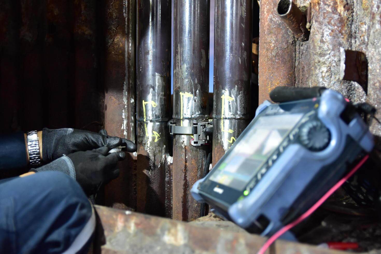
Robotic Video Crawler is an advanced borescope method to assess the internal conditions of tubes, Pipes, vessels, etc. , and record the observation in the movie format using remotely operated video Crawler equipment. The tubes and piping to be inspected shall have access to insert video Crawler and to carry out Visual inspection. By using this we can inspect piping greater than 10inch diameter. Visual examination is generally used to determine such things as the surface condition of the part, alignment of mating surfaces, corrosion, erosion, cracking, oxidization, distortion or evidence of leakage, bulging, sagging, etc. When Visual inspection is performed, the Video Crawler system shall have the same resolution as direct visual examination. The Video Crawler camera shall be articulated/focused, and the images shall be displayed as video or image formats. The results shall be recorded in the hard disk for future reference.
Application
Robotic Video Crawler is widely used in the oil & gas and petrochemical industries to assess the internal conditions of tubes, Pipes, vessels, tanks etc.,
FAQs:
- How does a Robotic Video Crawler work?
-
The crawler moves along surfaces using wheels or tracks while capturing high-resolution video and images. Some models include additional sensors like ultrasonic or laser scanners for detailed inspection data.
- What materials can be inspected using a Robotic Video Crawler?
-
It can inspect surfaces made of metal, concrete, and composite materials, making it ideal for industrial, marine, and underground inspections.
- What are the advantages of using a Robotic Video Crawler?
-
It allows safe, remote inspections in confined or hazardous spaces, provides real-time video analysis, and reduces the need for manual entry.
Electromagnetic Acoustic Transducer (EMAT) is a transducer for non-contact sound generation and reception using electromagnetic mechanisms. EMAT is an ultrasonic Non-destructive Testing (NDT) method which does not require contact or couplant, because the sound is directly generated within the material adjacent to the transducer. Due to this couplant-free feature, EMAT is particularly useful for automated inspection, and hot, cold, clean, or dry environments.
EMAT is an ideal transducer to generate Shear Horizontal (SH) bulk wave mode, Surface Wave, Lamb waves and all sorts of other guided-wave modes in metallic and/or ferromagnetic materials. As an emerging ultrasonic testing (UT) technique, EMAT can be used for thickness measurement, flaw detection, and material property characterization. Advantages are, Dry Inspection, Easier sensor deployment, Ability to generate SH modes, less sensitive to surface conditions.
Application
EMAT is widely used in Oil & gas Industry, chemical, metal manufacturing and processing, automotive, railroad, pipeline industries (In-service piping, Tubulars, Wall thickness under pipe support, Vessels)
FAQs:
- How does EMAT work?
-
EMAT induces ultrasonic waves directly into the material using a combination of a magnetic field and an electric current, eliminating the need for couplants like gels or liquids used in conventional ultrasonic testing.
- What materials can be tested using EMAT?
-
EMAT works best on conductive and ferromagnetic materials like steel, aluminum, and titanium, making it ideal for corrosion monitoring and weld inspection.
- What are the advantages of EMAT?
-
EMAT allows fast, non-contact inspections, works on rough or coated surfaces, and performs well in extreme temperatures or hazardous environments.

Magnetic Flux Leakage (MFL) is a non-destructive testing method used to detect and assess corrosion, erosion, and other forms of wall loss in ferromagnetic materials, such as steel pipelines, storage tanks, and vessels. A magnetic field is induced into the material being inspected using permanent magnets or electromagnets.
Sensors, typically Hall Effect sensors or magnetic field detectors, are placed on the surface of the material to measure the magnetic flux density. These sensors are arranged in an array to cover the entire surface being inspected.
The inspection tool, often called a “pig” in the case of pipelines, is inserted into the material, and it moves along the length of the material being inspected. As it moves, the sensors measure the magnetic flux leakage from the material’s surface. Any deviations in the magnetic flux pattern, caused by changes in the material’s thickness or the presence of defects like corrosion or erosion, are detected by the sensors.
The data collected by the sensors is analyzed to identify and characterize any anomalies detected during the inspection. This may involve determining the location, size, and severity of defects. The findings from the MFL inspection are documented in a report, which may include the location and dimensions of any detected anomalies, as well as recommendations for further action, such as repair or maintenance.
MFL is widely used in industries such as oil and gas, petrochemical, and pipeline transportation to assess the integrity of metallic structures and ensure safe and reliable operation. It is a valuable tool for detecting and monitoring corrosion and erosion, particularly in inaccessible or hard-to-reach areas, without the need for surface preparation or direct contact with the material being inspected.
FAQs:
- How does MFL work?
-
A strong magnetic field is applied to the material, and if there are defects, the magnetic flux "leaks" from the surface. Sensors detect these leaks, creating a signal that indicates the presence and size of defects.
- What materials can be tested using MFL?
-
MFL is used exclusively on ferromagnetic materials like iron and steel, as they can be effectively magnetized for inspection.
- Where is MFL commonly used?
-
MFL is widely used in oil and gas, petrochemical, and infrastructure industries for inspecting pipelines, storage tanks, and structural components.
Remote Field is a technique used for the inspection of tubes made of ferrous materials, like Carbon steel and Chrome-Molybdenum. RFT is only one of the techniques available for inspection of carbon steel tubes. Since al inspection techniques that are available for carbon steel have limitations compared to conventional eddy current, it is even more important to select the most suitable technique for each different situation.
For the inspection of carbon steel tubes it is often recommended to use a combination of one or more techniques. Overall wall-loss can be easily detected and accurately quantified. Local defect scan be detected and quantified provided that they have some volume (diameter pit >5 mm).
RFT can detect both in- and external defects but it is not possible to distinguish between them. Widely used in Steel, Automotive and Aerospace industries, the eddy current method is one of many electromagnetic testing methods used in Non-Destructive Testing (NDT). It makes use of electromagnetic induction to detect and characterize surface and sub-surface flaws in conductive materials.
FAQs:
- How does RFET work?
-
A low-frequency alternating current induces an electromagnetic field that travels through the tube wall, with sensors detecting field variations caused by defects. Unlike conventional eddy current testing, RFEC is highly sensitive to flaws on both the inner and outer surfaces.
- What materials can be tested using RFET?
-
RFET is specifically used for ferromagnetic materials like carbon steel, where traditional eddy current techniques have limited penetration.
- Where is RFET commonly used?
-
RFET is widely used in heat exchanger tubes, boiler tubes, and pipelines for corrosion monitoring, erosion detection, and structural integrity assessment.
Magnetic Flux Leakage testing (MFL) is a technique used for the inspection of tubes made of ferrous materials. This technique will normally be applied as a fast-screening technique if small diameter pitting is expected. Because of limitations to its sizing abilities Magnetic Flux Leakage testing is not often used as a stand-alone technique, and verification by other techniques is recommended. An advantage of MFL Testing for inspections is that it can also be used on fin-fan cooler tubes.
The probe in the MFL Testing technique contains permanent magnets which are utilized to form a magnetic flux field in the tube wall.
Defects will influence the path of the magnetic field and will cause some of the flux to leak out of the tube wall. This leakage field will be picked up by the coils and the Hall-effect sensors in the probe. Size of the leakage field is determined by pull speed of the probe and by the shape, the dimensions and the location of defects. Signals that represent the size of the leakage field and thus the condition of the tube are presented on a computer screen.
FAQs:
- How does MFL for Tubular Inspection work?
-
A strong magnetic field is applied to the tube, and any defects cause disruptions (leakage) in the magnetic field. Sensors detect these changes and generate data to identify the size and location of flaws.
- What materials can be tested using MFL for Tubular Inspection?
-
MFL is specifically used for ferromagnetic materials like carbon steel, making it ideal for inspecting heat exchanger tubes, boiler tubes, and pipelines.
- Where is MFL for Tubular Inspection commonly used?
-
It is widely used in industries such as oil and gas, chemical processing, and power plants for inspecting pipelines, refinery equipment, and heat exchanger tubes.

Time of Flight Diffraction (TOFD) is a reliable and fastest method of nondestructive ultrasonic testing (UT) used to look for flaws in welds. TOFD uses the time of flight of an ultrasonic pulse to find the location of a reflector. It can also be used for weld overlays and the heat affected zones of other components as well such as piping, pressure vessels, clad material, storage tanks and structural steel. PAUT + TOFD combination is commonly used to inspect pipeline welds. To do this, TOFD uses a pair of ultrasonic transducers, one as a transmitter and the other as a receiver. The low frequency waves propagate at an angle and only diffract back to the receiver if they hit a defect. If this happens, the time it takes for both waves to make it to the receiver can be used to create a complete image of the weld and identify the size and location of the damage. Advantages are, high degree of repeatability, no radiation, higher POD, cost saving, more sensitive, Quick setup, precise sizing.
Application
TOFD is widely used in Oil & gas Industry, nuclear, (Refinery’s, Petrochemicals of piping, pressure vessels, clad material, In-service weld inspection)
FAQs:
- How does TOFD work?
-
TOFD uses two ultrasonic probes placed on opposite sides of a weld; one emits sound waves while the other receives diffracted signals from defect edges. By measuring the time taken for these signals to return, defect size and location can be accurately determined.
- What materials can be tested using TOFD?
-
TOFD is used on metals like steel, aluminum, and titanium, making it ideal for weld inspections, pressure vessels, and pipeline integrity assessments.
- Where is TOFD commonly used?
-
TOFD is widely used in industries such as oil and gas, nuclear power, and construction for weld inspection, pipeline monitoring, and structural integrity assessments.

Phased Array Ultrasonic Testing (PAUT) is an advanced nondestructive examination technique that utilizes a set of ultrasonic testing (UT) probes made up of numerous small elements, each of which is pulsed individually with computer-calculated timing. more complex geometries that are difficult. PAUT can be used for more complex geometric weld inspections, high thick materials and crack detection. Advantages are, it can be conducted more quickly, used for repeat scans because it has a high degree of repeatability, it is able to create detailed and accurate cross-sections of a part, gives a permanent record, Gives information about lateral position of defect in weld (depth and height), No radiation, higher POD.
Application
PAUT is widely used in Oil & gas, nuclear Industries (Refinery’s, Petrochemicals of piping, boilers, pressure vessels, clad material, Storage Tanks, In-service weld inspection including Stress Corrosion Cracking, Complex Geometries – Nozzles, Flanges, Shafts, bolts).
FAQs:
- How does PAUT work?
-
PAUT uses an array of ultrasonic transducers that can be electronically controlled to steer and focus sound waves at different angles. This allows for precise imaging of defects, making it more efficient than conventional ultrasonic testing (UT).
- What materials can be tested using PAUT?
-
PAUT is used on metals, composites, and ceramics, making it suitable for inspecting welds, pressure vessels, pipelines, and aircraft structures.
- What are the advantages of PAUT?
-
PAUT provides high-resolution imaging, faster inspection times, and improved defect detection capabilities while reducing the need for multiple probe setups.

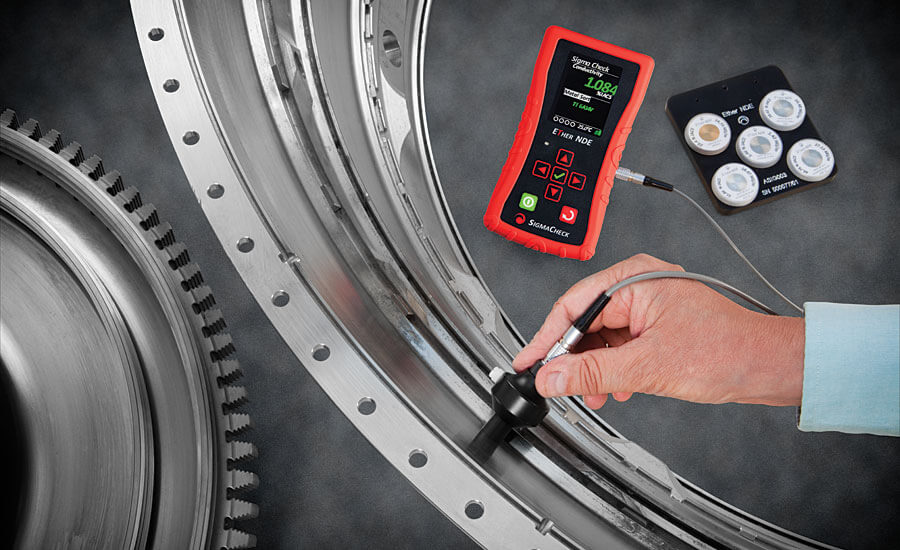
Eddy currents are created through a process called electromagnetic induction. When alternating current is applied to the conductor, such as copper wire, a magnetic field develops in and around the conductor. This magnetic field expands as the alternating current rises to maximum and collapses as the current is reduced to zero. If another electrical conductor is brought into close proximity with this changing magnetic field, current will be induced in this second conductor.
Eddy currents are induced electrical currents that flow in a circular path. They get their name from Tripex Consultants Limited 12 Eddies, which are formed when a liquid or gas flows in a circular path around obstacles when conditions are right. ID probes, which are also referred to as Bobbin probes or feed-through probes, are inserted into hollow products, such as pipes, to inspect from the inside out.
ID probes have housing that keeps the probe centered in the product and the orientation of the coil(s) somewhat constant relative to the test surface. The coils are most commonly wound around the circumference of the probe so that the probe inspects an area around the entire circumference of the test object in one go.
API 653 is a standard published by the American Petroleum Institute (API) that provides guidelines for the inspection, repair, alteration, and reconstruction of aboveground storage tanks (ASTs) used in the petroleum and chemical industries. The standard covers various types of ASTs, including those for storing crude oil, refined products, chemicals, and other liquids.
API 653 tank inspection involves a comprehensive examination of the tank’s integrity to ensure safe operation and compliance with regulatory requirements.
FAQs:
- How does ECT work?
-
An alternating current flows through a coil, creating a magnetic field that induces eddy currents in the test material. Changes in these currents, caused by defects, are detected and analyzed to assess the material’s condition.
- What materials can be tested using ECT?
-
ECT is used on conductive materials like aluminum, copper, and steel, making it ideal for inspecting metal components and coatings.
- What are the advantages of ECT?
-
ECT is fast, does not require direct contact, and can detect small cracks, corrosion, and thickness variations without damaging the material.

Radiographic Testing (RT) is a non-destructive testing method used to detect internal defects and evaluate the internal structure of materials. It involves the use of X-rays or gamma rays to penetrate the material being inspected. Radiographic Testing is commonly used in industries such as aerospace, automotive, construction, and manufacturing to assess welds, castings, forgings, and other components for defects such as cracks, voids, inclusions, and porosity. X-rays or gamma rays are generated by a radiation source (X-ray tube or radioactive isotope) and directed towards the material being inspected.
The radiation penetrates the material, and a portion of it is absorbed or attenuated based on the material’s density and thickness. A film or digital detector is placed on the opposite side of the material. As the radiation passes through the material, it interacts with the film or detector, resulting in the formation of a latent image.
For film-based radiography, the exposed film is developed using a chemical process to reveal the latent image. For digital radiography, the captured image is processed electronically. Trained technicians interpret the radiographic images to identify and evaluate any indications or anomalies present. This may involve comparing the radiographic image to applicable standards, specifications, or reference images. The findings from the radiographic examination are documented in a report, which may include the location, size, and nature of any detected indications, as well as recommendations for further action if necessary.
Radiographic Testing can provide detailed information about the internal condition of materials, making it a valuable tool for detecting defects that may not be visible to the naked eye. However, it requires specialized equipment and trained personnel to perform safely and effectively. Additionally, radiation safety precautions must be strictly followed to protect personnel and the environment from potential hazards associated with ionizing radiation.
FAQs:
- How does RT work?
-
A radiation source passes through the material onto a detector or film, creating an image that reveals internal flaws such as cracks, voids, and inclusions based on differences in material density.
- What materials can be tested using RT?
-
RT can be used on metals, composites, ceramics, and plastics, provided they allow sufficient radiation penetration for imaging.
- What are the advantages of RT?
-
It provides a permanent record of the inspection and can detect both surface and internal defects without damaging the material.